
How to Read Blueprints for Your Project Success
Most American construction projects begin with detailed blueprints, yet over 60 percent of new builders admit they struggle to read these technical drawings accurately. Understanding blueprint symbols and interpreting complex architectural diagrams is critical for avoiding expensive mistakes and keeping projects on track. This guide breaks down the essentials of blueprint reading so anyone on an American jobsite—from homeowners to professionals—can confidently translate lines and symbols into real-world results.
Table of Contents
- Step 1: Understand Blueprint Symbols And Legends
- Step 2: Identify Key Sections And Plan Types
- Step 3: Interpret Scale, Dimensions, And Notes
- Step 4: Verify Construction Details And Specifications
- Step 5: Apply Blueprint Knowledge To Site Evaluation
Quick Overview
| Key Insight | Explanation |
|---|---|
| 1. Understand blueprint symbols early | Familiarize yourself with architectural symbols and their meanings to easily decode blueprints and communicate construction specifics. |
| 2. Recognize essential blueprint sections | Identify key plan types like site, floor, elevation, and cross-section plans to understand their unique roles in design communication. |
| 3. Master scale and dimensions | Learn how scales translate drawing measurements to real-world dimensions, ensuring accurate interpretation of plans. |
| 4. Verify details and specifications | Meticulously check material specifications and building codes to ensure compliance and avoid construction errors. |
| 5. Apply blueprint knowledge on-site | Use site plans during property evaluations to align theoretical designs with actual conditions, noting any discrepancies for correction. |
Step 1: Understand blueprint symbols and legends
Blueprint symbols are the secret language of design and construction professionals. When you first look at architectural drawings, these intricate marks can seem like cryptic code. Understanding architectural symbols and legends transforms these complex graphics into clear communication tools that reveal precise building details.
Each symbol represents a specific material, component, or construction technique. For instance, different line styles and shapes communicate unique information about walls, windows, electrical systems, and more. Solid lines might indicate existing structures, while dashed lines could represent proposed changes. Specialized symbols help engineers and architects convey exact specifications without lengthy written explanations. Some common categories include material symbols, graphic symbols for equipment, and directional indicators that show orientation and workflow.
To decode these symbols effectively, always start by examining the legend carefully. The legend acts as your blueprint translation guide, explaining what each mark represents. Pay special attention to line thickness, color coding, and graphic patterns. Some symbols might seem similar but have critically different meanings, so precision matters. Professional blueprint readers develop an intuitive understanding of these visual languages through practice and systematic study.
Professional tip: Create a personal reference sheet where you quickly sketch and note down unfamiliar symbols during your first review. This hands-on approach helps internalize complex graphic languages faster than passive reading.
Step 2: Identify key sections and plan types
Understanding blueprint organization is crucial for successful project planning. Architectural drawings reveal complex design specifications through multiple interconnected sections that each serve a unique purpose in communicating construction details.

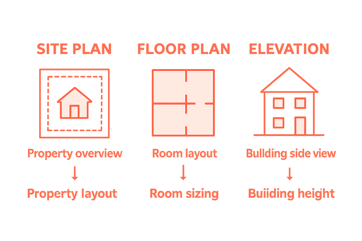
Blueprints typically include several essential plan types. Site plans provide an overhead view of the entire property, showing building placement, property lines, and exterior features. Floor plans offer a bird’s eye view of interior spaces, detailing room layouts, dimensions, and structural elements. Elevation plans showcase the building’s exterior views from different angles, illustrating height, materials, and architectural features. Cross section plans slice through the building vertically, revealing interior structural relationships and construction techniques. Mechanical, electrical, and plumbing plans add specialized layers that show precise system configurations and technical specifications.
Here’s a quick reference summary of common blueprint plan types and what they reveal:
| Plan Type | Main Purpose | Key Information Provided |
|---|---|---|
| Site Plan | Shows property layout and context | Building location, boundaries |
| Floor Plan | Maps internal arrangements | Room sizes, wall placement |
| Elevation Plan | Displays building from exterior views | Materials, heights, architectural features |
| Cross Section | Slices through the structure vertically | Construction methods, components |
| MEP Plans | Diagrams technical systems | Mechanical, electrical, plumbing layouts |
To effectively navigate these plan types, develop a systematic approach. Start by examining the site plan to understand overall context, then move through floor plans, elevations, and specialized technical drawings. Pay attention to scale notations, which indicate the proportional relationship between the drawing and actual dimensions. Each plan type communicates different information, so understanding their collective purpose helps you grasp the complete design intent.
Professional tip: Create a checklist of plan types before reviewing blueprints, ensuring you methodically review each section and do not miss critical design details.
Step 3: Interpret scale, dimensions, and notes
Mastering blueprint reading requires understanding how architectural drawings translate real world measurements through precise scales and detailed notations. These visual communication tools transform complex design concepts into actionable information that guides construction professionals and property owners.
Scale represents the proportional relationship between the drawing and actual physical dimensions. Typical architectural scales range from 1/4 inch equals 1 foot to 1/8 inch equals 1 foot for floor plans, while detailed sections might use larger scales like 1/2 inch equals 1 foot. Always locate the scale notation first typically found in a corner of the drawing. Use a standard architectural scale ruler to accurately measure and translate drawing dimensions to real world measurements. Dimensions are usually written directly on the drawing with numerical values indicating exact lengths, widths, and heights. Pay special attention to notes accompanying dimensions which often provide critical additional context about materials, construction methods, or specific requirements.
Use this table to compare blueprint scale types and their best uses:
| Scale Type | Typical Ratio | Best Used For |
|---|---|---|
| Architectural | 1/4" = 1’ or 1/8" = 1’ | General floor plans |
| Larger Detail | 1/2" = 1’ or 1" = 1’ | Sections, fine details |
| Engineering | 1" = 10’ or 1" = 20’ | Site plans, land surveys |
When interpreting dimensions, start by understanding the primary measurements for key structural elements like room sizes, wall heights, and window placements. Cross reference these measurements with scale notations to ensure accuracy. Look for annotations that might modify standard dimensions such as notes about special construction techniques, material specifications, or design variations. Architectural notes can include critical information about structural requirements, material selections, and specific installation instructions that are not visually represented in the drawing.
Professional tip: Always keep a sharp architectural scale ruler and calculator nearby when reviewing blueprints to quickly verify and convert measurements across different scales.
Step 4: Verify construction details and specifications
Verifying construction details requires a methodical approach to understanding the intricate specifications outlined in construction drawing documentation. Your goal is to thoroughly examine every technical specification to ensure complete project alignment and prevent potential construction errors.
Start by meticulously reviewing material specifications for each component. Check detailed notes about concrete mix ratios, steel reinforcement requirements, wood grades, insulation types, and specific manufacturer recommendations. Pay close attention to specialized annotations that indicate unique construction requirements or performance standards. Look for callout boxes or marginal notes that describe critical installation techniques, tolerance levels, or specific engineering constraints that might not be immediately visible in the primary drawing views.
Compare the technical specifications against industry standard building codes and local regulatory requirements. Verify that all proposed materials and construction methods meet or exceed minimum performance standards. Cross reference detailed specifications with general notes sections, ensuring consistency across different drawing sheets. Watch for potential conflicts between architectural, structural, mechanical, and electrical plan specifications that could create implementation challenges during actual construction.
Professional tip: Create a comprehensive specification checklist before beginning your detailed review, systematically marking off each verified specification to ensure nothing gets overlooked during your blueprint examination.
Step 5: Apply blueprint knowledge to site evaluation
Transferring blueprint insights to actual site conditions requires a strategic approach that combines precise drawing interpretation with practical field observation. Site plans provide critical visual representations that bridge the gap between theoretical design and physical reality.
Begin by using the site plan as your primary reference when walking the property. Compare the blueprint measurements and property boundaries against the physical landscape. Look for key reference points like property corners, existing structures, utility connections, and topographical features. Pay special attention to elevation markers and contour lines that indicate ground slope and potential drainage challenges. Identify potential obstacles not immediately apparent in the drawings such as underground utility lines, rock formations, or existing vegetation that could impact construction feasibility.
Carefully analyze floor plan relationships and spatial configurations to understand how proposed structures will interact with the existing site conditions. Consider factors like sunlight exposure, wind patterns, natural drainage routes, and potential environmental constraints. Verify that theoretical design specifications align with actual ground conditions. Note any discrepancies between blueprint representations and physical site characteristics that might require design modifications or additional engineering interventions.
Professional tip: Take comprehensive site photographs that document existing conditions and align them with specific blueprint sections to create a visual reference library for future project planning and design refinement.
Master Blueprint Reading with Expert Engineering Support
Reading blueprints is essential for the success of any residential or commercial project. This article highlights common challenges like understanding complex symbols, interpreting scales, and verifying detailed construction specifications. Without precise knowledge, mistakes can lead to costly delays or design conflicts. You deserve clear, reliable guidance to navigate architectural, structural, mechanical, electrical, and plumbing plans with confidence.

Take control of your project by partnering with seasoned professionals. At Florida Licensed Engineers, we specialize in comprehensive engineering services, including blueprint interpretation, inspections, permitting expediter services, and civil engineering solutions such as drainage and flood mitigation analysis. Our expertise will help you avoid costly errors and move smoothly from blueprint to build. Explore more about our offerings in the TLE Archives – Texas Licensed Engineers | Residential & Commercial and get started today. Don’t wait—secure your project’s success now by visiting Florida Licensed Engineers.
Frequently Asked Questions
How do I begin reading blueprints for my construction project?
To start reading blueprints, familiarize yourself with blueprint symbols and legends, as they provide key information about materials and components. Review the legend carefully to decode each symbol, taking notes on unfamiliar symbols to enhance your understanding.
What are the different types of plans included in blueprints, and what do they represent?
Blueprints typically include site plans, floor plans, elevation plans, cross-section plans, and mechanical, electrical, and plumbing plans. Each type serves a specific purpose, such as illustrating property layouts or detailing internal arrangements, so examine them in sequence to grasp the full design intent.
How do I interpret dimensions and scales in architectural drawings?
To interpret dimensions and scales effectively, first locate the scale notation usually found in a corner of the drawing. Use an architectural scale ruler to measure and translate the blueprint dimensions into real-world measurements, ensuring accuracy in your project planning.
What should I verify in construction details and specifications outlined in blueprints?
When verifying construction details, closely examine material specifications, unique annotations, and cross-reference these with industry standards and building codes. Create a comprehensive specification checklist to ensure all requirements are met and nothing is overlooked during your project review.
How can I apply my blueprint knowledge to evaluate a construction site?
Apply your blueprint knowledge by using the site plan as a primary reference when walking the property. Compare the blueprint measurements with the actual site layout and observe any discrepancies that may require design adjustments or additional engineering considerations.
What is the best way to document my observations during a site evaluation based on blueprints?
To document your site evaluation observations, take comprehensive photographs that align with specific sections of the blueprints. Organize these images to create a visual reference library that aids in future project planning and refining design details.
Recommended
- Complete Guide to the Role of Blueprints – FloridaLicensedEngineers.com
- Complete Guide to Blueprints for Residential Projects – FloridaLicensedEngineers.com
- Architectural Plans Explained: Complete Guide for 2025 – FloridaLicensedEngineers.com
- How to Create Architectural Drawings for Your Project – FloridaLicensedEngineers.com
