
Role of Mechanical Plans in Project Success
Overseeing a construction site in Florida comes with unique challenges, especially when mechanical plans determine whether your HVAC or plumbing systems function seamlessly or run into costly setbacks. The state’s demanding heat and humidity mean your blueprints must go beyond the basics and reflect both Florida Building Code requirements and on-site realities. Mastering mechanical systems drawings ensures every piece of equipment, pipe, and duct is coordinated, compliant, and ready to deliver lasting performance for your clients.
Table of Contents
- What Mechanical Plans Represent in Construction
- Essential Types of Mechanical Plans Explained
- Core Features and Technical Components
- Integrating Mechanical Plans with Other Disciplines
- Compliance with Florida Codes and Standards
- Common Pitfalls and Financial Implications
Key Takeaways
| Point | Details |
|---|---|
| Importance of Mechanical Plans | Mechanical plans are essential blueprints that guide installation and ensure compliance with building codes. They prevent costly mistakes, delays, and budget overruns during construction. |
| Types of Mechanical Plans | Different types of mechanical plans, such as HVAC, plumbing, and piping schematics, serve specific purposes and are critical for effective coordination among trades. |
| Compliance with Florida Standards | Mechanical plans must meet the 2023 Florida Building Code to avoid permit rejections and ensure safety and efficiency in Florida’s unique climate. |
| Avoiding Common Pitfalls | Key pitfalls in mechanical planning include designing without collaboration and creating incomplete plans, which can lead to expensive change orders and operational inefficiencies. |
What Mechanical Plans Represent in Construction
Mechanical plans are the technical blueprints that translate your HVAC, plumbing, and other building systems from concept into actionable installation instructions. These aren’t optional design documents that sit in a drawer. They’re working documents that contractors, engineers, and inspectors reference continuously throughout your project. For residential and commercial projects in Florida, mechanical plans serve as the critical link between what’s been designed and what actually gets installed on site.
Think of mechanical plans as a complete communication system for your project. Mechanical systems drawings represent heating, ventilation, air conditioning, and other critical building systems through detailed technical drawings that include arrangement, assembly, detail, and fabrication drawings. Each drawing layer shows specific information: dimensions that tell installers exactly where equipment goes, component specifications that verify quality and compatibility, material requirements that affect both budget and timeline, and assembly instructions that prevent costly mistakes during installation. When you’re managing a commercial office building in Tampa or a residential complex in Miami, these drawings become your insurance policy against installation errors, permit rejections, and system failures that would cost far more to fix later.
The practical value becomes clear when you step on site. Your electrical contractor needs to know where the HVAC returns pull from the walls. Your framing crew needs to understand ductwork routing before they seal up cavities. Your permitting process depends on submitting detailed mechanical plans that prove your systems meet Florida building codes and energy efficiency standards. Without complete, accurate mechanical plans, you’re essentially asking your team to guess, and guessing on mechanical systems is how budgets explode and timelines slip. These documents also become permanent parts of your construction record, required for everything from warranties to future renovations to insurance claims.
Mechanical plans carry additional weight in Florida specifically. Our climate demands robust HVAC systems that handle intense heat and humidity, and our permitting authorities require documentation that proves you’re meeting those demands. The plans demonstrate compliance with Florida Building Code requirements, establish accountability for system performance, and protect you legally by creating a paper trail showing what was specified versus what was actually installed. Whether you’re coordinating with mechanical contractors, working through permit reviews, or managing change orders mid-project, these plans are your reference point.
Pro tip: Request complete mechanical plans during the design phase before construction begins, not after, so you can coordinate with other trades and catch conflicts with structural elements or electrical routing that would otherwise delay installation.
Essential Types of Mechanical Plans Explained
Mechanical plans aren’t one-size-fits-all documents. Different aspects of your building’s systems require different types of drawings, each serving a specific purpose during design, permitting, and construction. Understanding what each type shows helps you communicate better with your mechanical engineer, catch problems before they become expensive, and ensure nothing gets missed during installation. For contractors and architects managing Florida projects, knowing these distinctions separates smooth construction from the kind of delays that eat into profit margins.
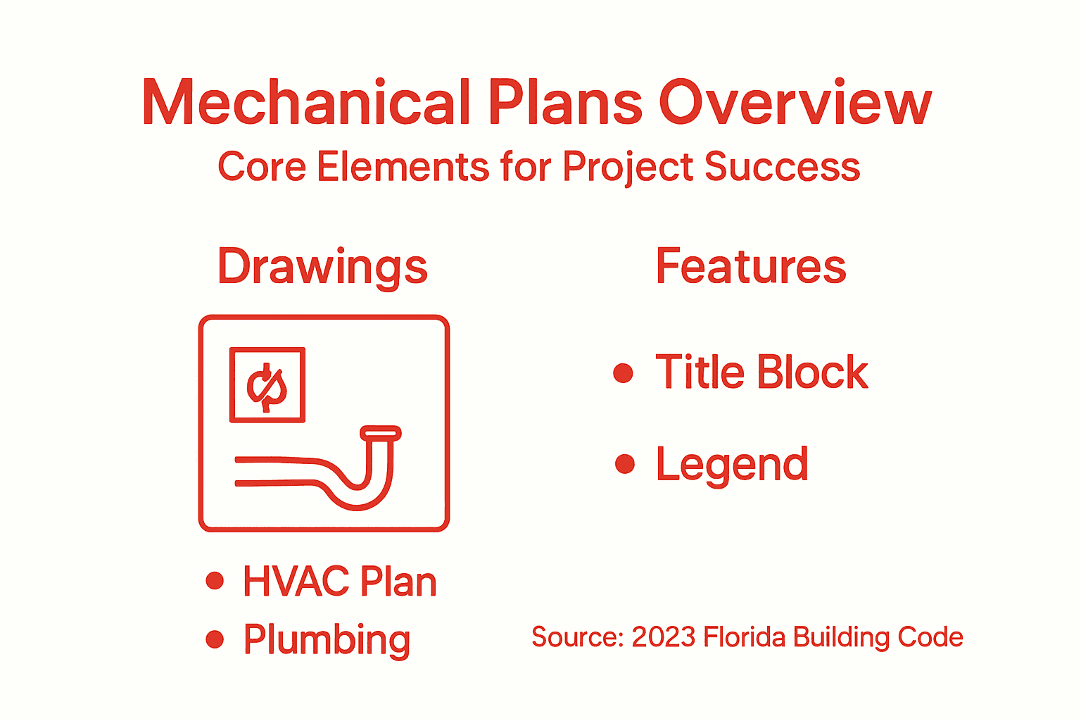
The primary categories break down based on what system you’re documenting. HVAC plans detail your heating, ventilation, and air conditioning layouts, showing ductwork paths, equipment locations, return air configurations, and airflow directions. Plumbing plans map out water supply lines, drain and vent piping, fixture locations, and pressure requirements. Piping schematics go deeper into the mechanical systems, illustrating how components connect and interact. These aren’t interchangeable. An HVAC plan tells installers where ducts run, but a piping schematic shows how refrigerant flows through your cooling system. MEP drawings coordinate mechanical, electrical, and plumbing systems to ensure clash-free execution and prevent the conflicts that occur when a ductwork run collides with electrical conduit or plumbing lines. On a typical commercial project in Jacksonville or a residential renovation in Orlando, you’re working with multiple mechanical plan types simultaneously, and they all need to work together without conflicts.
Within each major category, you’ll see specialized drawing types. Layout drawings show the big picture: where equipment sits, how systems distribute throughout the building, and overall routing. Detail drawings zoom in on specific connections, showing exactly how components bolt together, what size fasteners you need, and how seals and gaskets get installed. Isometric drawings provide three-dimensional representation that helps contractors visualize complex piping runs or ductwork that’s tough to understand from top-down views. Assembly drawings illustrate how sub-components combine into finished systems. Each type serves a different audience. Your mechanical installer needs layout drawings to understand overall system placement. Your fabrication shop needs detail drawings with precise specifications to manufacture custom ductwork or manifolds. Your inspector needs drawings that prove everything meets code.
The distinction matters most when you’re coordinating trades. Your mechanical contractor can’t start running ductwork until they know where electrical rough-in is happening. Your structural team needs to understand piping loads before finalizing support locations. Your mechanical plans become the communication tool that prevents these conflicts. In Florida projects, where humidity and heat create demanding HVAC requirements, mechanical plans also document compliance with energy codes and building standards that permit reviewers will scrutinize carefully.
Here’s a summary of the main categories of mechanical plans and their unique contributions:
| Plan Type | Main Purpose | Who Uses It |
|---|---|---|
| HVAC Plans | Detail heating, cooling, airflow | Installers, engineers |
| Plumbing Plans | Map water supply and drainage | Plumbers, contractors |
| Piping Schematics | Show system connections and flow | Fabricators, inspectors |
| MEP Drawings | Coordinate all major systems | All project stakeholders |
Pro tip: Request isometric or three-dimensional mechanical drawings for complex systems like rooftop HVAC units or multi-floor plumbing risers, since these views prevent field confusion and costly installation errors that 2D drawings sometimes create.
Core Features and Technical Components
Every mechanical plan you encounter follows a consistent structure that communicates information to different stakeholders. Understanding what each element means prevents misinterpretation and catches errors before they reach the job site. When you’re coordinating between your mechanical engineer, contractors, and permit reviewers, knowing what information appears where makes those conversations clearer and faster. The technical components on a mechanical plan aren’t randomly placed. They follow industry standards that allow anyone familiar with construction to read and understand the document.
The foundation of every mechanical plan starts with the title block, which sits in the corner of the drawing and contains critical project data: your project name, location, client name, the engineer who designed it, the date of the drawing, and revision numbers. Below that, you’ll find a comprehensive legend that decodes all the symbols used throughout the drawing. Different contractors use slightly different symbol conventions, so the legend eliminates guesswork. You’ll see symbols for dampers, valves, equipment connections, and flow directions. The legend is your key to understanding the entire drawing. Mechanical plans include detailed dimensions and tolerances, system connections and flow directions, and installation and material specifications that ensure accurate understanding and integration of mechanical components with other building systems. On a commercial project in Miami or a residential renovation in Tampa, these specifications prevent the kind of installation mistakes that require costly rework.

Beyond the legend, mechanical plans display dimensional information that tells installers exactly where equipment goes and how systems connect. You’ll see measurements showing ductwork centerline locations, equipment clearances, and pipe routing paths. Flow direction arrows indicate how air, water, or refrigerant moves through your systems. Connection details show how pipes, ducts, and equipment bolt together, including bolt sizes, gasket types, and seal specifications. Material callouts specify what type of ductwork, pipe, or insulation to use. In Florida’s humid climate, insulation specifications matter tremendously because inadequate insulation leads to condensation problems that damage buildings. Equipment schedules appear as tables that list every piece of mechanical equipment, including model numbers, capacities, and performance ratings. This schedule becomes your procurement checklist and helps your contractor order the right parts.
The technical layers build on each other to create a complete picture. A set of mechanical plans typically includes the overall system layout, detailed connection drawings, isometric views of complex runs, and schedules that specify everything from equipment models to pipe materials. Each layer serves a purpose. Your installer needs the overall layout to understand where to run ductwork. Your inspector needs the detail drawings to verify installations meet code. Your facility manager needs the schedules to order replacement parts five years later. When these components are missing or unclear, that’s when field crews improvise, which rarely ends well.
Pro tip: Request a coordination drawing that overlays mechanical, electrical, and plumbing systems on the same sheet before purchasing long-lead equipment, so you can identify conflicts early and avoid expensive mid-project redesigns.
Integrating Mechanical Plans with Other Disciplines
Mechanical plans don’t exist in isolation. They intersect with structural systems, electrical systems, plumbing systems, and architectural layouts in ways that determine whether your project runs smoothly or spirals into coordination chaos. When these plans fail to communicate effectively across disciplines, you get ductwork that collides with structural beams, pipe runs that block electrical conduit, and HVAC equipment that doesn’t fit in the space the architect designed. For contractors and architects managing Florida projects, integration failures translate directly into change orders, schedule delays, and budget overruns that could have been prevented with better coordination.
The structural discipline sets hard constraints that mechanical systems must work around. Your mechanical engineer needs to know where columns sit, what beam depths exist, and how much load capacity the structure can handle for equipment support. A rooftop HVAC unit weighing 5 tons requires specific structural support points that the structural engineer must size accordingly. If the mechanical plan assumes support points that don’t align with the structural grid, you’re looking at expensive modifications mid-construction. The mechanical design process for construction projects requires coordination with structural elements from the earliest design phases. Similarly, your electrical plans show power supply locations, panel placements, and equipment clearances that mechanical systems must respect. An HVAC condensing unit needs adequate clearance around it for maintenance and airflow, but that space can’t conflict with electrical equipment or service areas. The plumbing systems bring additional complexity. Vertical piping runs, drain stacks, and water supply lines occupy wall cavities and chase spaces that mechanical ductwork might also want to use. Without coordination, you end up forcing systems to take inefficient routes that increase costs and reduce performance.
The architectural drawings provide the overall spatial framework that everything else fits into. Ceiling heights, wall locations, room layouts, and equipment room sizes all constrain what mechanical systems can actually accomplish. Your architect might design a beautiful open ceiling for a retail space, but your mechanical contractor needs to know if there’s room above that ceiling for ductwork distribution. In Florida’s hot, humid climate, that coordination is crucial because HVAC systems often require more ductwork capacity than buildings in milder climates. The architectural plans also show where walls exist, which determines whether you can run horizontal ductwork runs or need to go vertical through mechanical shafts. When these conversations happen early in design, before detailed drawings are created, changes are inexpensive. When coordination issues emerge during construction, they become expensive lessons.
Effective integration requires regular coordination meetings where representatives from each discipline review overlaid plans together. Many contractors use BIM technology or digital coordination drawings that overlay all systems on a single sheet, making conflicts visible before anyone picks up a tool. On smaller Florida residential projects, the conversation might happen around a conference table with printed drawings. On large commercial projects, coordination software prevents conflicts systematically. The key principle remains the same: communicate early, update regularly, and resolve conflicts in the design phase.
Pro tip: Schedule a formal coordination meeting with your mechanical, structural, electrical, and plumbing engineers before releasing plans for permit review, using a combined drawing that shows all systems overlaid to catch conflicts in design rather than during construction.
Compliance with Florida Codes and Standards
Mechanical plans aren’t just design documents. They’re compliance documents that prove your systems meet mandatory Florida requirements before a single piece of equipment gets installed. The Florida Building Code sets specific standards that your mechanical systems must satisfy, and your mechanical plans become the evidence that you’ve met those standards. Permit reviewers will scrutinize your plans against code requirements, and if something doesn’t align, your project gets rejected and sent back for revisions. Understanding what Florida requires prevents costly rejections and delays that push timelines and budgets off track.
The governing standard in Florida is the 2023 Florida Building Code. The 2023 Florida Building Code Mechanical, 8th Edition governs mechanical systems within Florida, incorporating national standards along with Florida-specific amendments that address the state’s unique climate and environmental challenges. This code covers HVAC systems, refrigeration, exhaust systems, and duct configurations with particular emphasis on energy efficiency and indoor air quality. Florida’s hot, humid climate creates specific demands that the code addresses directly. Your HVAC systems must maintain proper humidity control to prevent mold growth and structural damage. Your ductwork must be sized and sealed to prevent energy loss in the heat. Your equipment must withstand the corrosive effects of salt air in coastal areas. Your mechanical plans must demonstrate that your selected equipment, ductwork sizing, refrigerant choices, and installation methods all comply with these requirements. When permit reviewers examine your plans, they’re checking whether your HVAC tonnage is appropriate for the building size, whether your ductwork follows proper installation practices, whether your exhaust systems properly terminate outside the building, and whether your indoor air quality provisions meet code minimums.
The code also emphasizes resilience against environmental challenges. Florida experiences high humidity year-round, intense afternoon thunderstorms that stress drainage systems, and hurricane-force winds that require secure equipment mounting and ductwork bracing. Your mechanical plans must show that equipment is properly secured to structural supports with the right fasteners and bracing to survive wind loads. Rooftop units need specific bracing patterns. Ductwork needs support spacing that prevents sagging and separation under its own weight plus pressure forces. Outdoor equipment needs corrosion-resistant coatings or materials that withstand salt air exposure. The role of engineers in building codes compliance involves detailed review of mechanical plans to ensure all these Florida-specific requirements are addressed before submission to permitting authorities.
Compliance documentation extends beyond just meeting the code minimums. Your mechanical plans must clearly show equipment specifications, nameplate capacities, installation details, and material selections in ways that allow inspectors to verify compliance during construction. When ductwork is hidden behind walls or in concrete, the only record that it was installed correctly is your mechanical plans. When HVAC equipment is on the roof, your installation drawings prove it was mounted according to code-required bracing patterns. This documentation protects you legally and ensures that your building performs as designed throughout its operational life.
Pro tip: Have your mechanical engineer cross-reference your plans against the current 2023 Florida Building Code before submitting to permit review, explicitly calling out code compliance for HVAC sizing, ductwork sealing methods, equipment bracing, and humidity control specifications to prevent permit rejections.
Common Pitfalls and Financial Implications
Mechanical plans fail in predictable ways, and each failure hits your budget in different ways. Some failures cost money upfront through permit rejections and redesigns. Others cost money for years afterward through inefficient operations and constant maintenance. Understanding these pitfalls helps you avoid them. For contractors and architects managing Florida projects, recognizing these patterns before they affect your project is the difference between profitable work and projects that drain resources.
The most expensive pitfall is designing mechanical systems without understanding how they’ll actually operate in Florida’s climate. Poor mechanical system design leads to hidden costs such as increased energy consumption and higher maintenance expenses, with initial construction costs representing only a small fraction of total lifecycle expenses. An undersized HVAC system will struggle in Florida heat and run constantly, consuming excess electricity and wearing out faster. An oversized system cycles inefficiently and costs more upfront. Get the sizing wrong in design, and you’re paying the penalty for years. A commercial office building sized incorrectly might waste 15 to 20 percent on energy bills annually. Over a 20-year building lifecycle, that’s real money. Inadequate humidity control in mechanical plans creates mold growth and structural damage that shows up months after construction concludes, triggering warranty claims and litigation. These aren’t minor oversights. They’re expensive mistakes that mechanical plans should prevent.
Another critical pitfall is designing without collaboration between disciplines. Common mechanical design problems include inadequate analysis, lack of collaboration, and rushed timelines, resulting in budget overruns and project delays. When the mechanical engineer designs HVAC ductwork without knowing where the structural engineer placed beams, you end up relocating ductwork mid-construction. When plumbing and mechanical share the same chase space and nobody coordinates, you’re paying for emergency redesigns. When the electrical panel is placed where the HVAC condensing unit needs outdoor clearance, change orders multiply. These coordination failures typically cost 5 to 15 percent in change orders on projects where they occur. On a 500,000-dollar project, that’s 25,000 to 75,000 dollars in preventable costs.
Rushed timelines create incomplete mechanical plans that leave critical decisions to field crews. When mechanical plans arrive on site with missing details about ductwork sizing, equipment specifications, or connection methods, contractors either guess or call for clarifications that stop work. Each day of delay costs money. Incomplete plans also lead to material ordering mistakes, requiring expedited shipping or replacement orders. Specification errors result in receiving the wrong equipment model, leading to returns and rewording.
These pitfalls compound when buildings operate poorly long term. Enhancing system design improves air quality, occupant comfort, and building value, providing significant financial benefits over time. Buildings with excellent mechanical design rent faster, command premium pricing, and retain tenants longer. Buildings with poor mechanical performance develop reputations for discomfort, high utilities, and maintenance issues that drive tenants away.
The table below shows common pitfalls in mechanical planning and their long-term financial impacts:
| Pitfall | Immediate Cost | Long-Term Financial Effect |
|---|---|---|
| Incorrect HVAC sizing | Redesigns, delay penalties | High energy bills, early failures |
| Poor trade coordination | Change orders, rework costs | Ongoing maintenance expenses |
| Incomplete documentation | Job stoppages, rush shipping | Facility inefficiencies, lawsuits |
Pro tip: Invest in detailed mechanical plans during design that address Florida humidity, hurricane bracing, and energy efficiency requirements, since that upfront investment prevents 10 to 20 times its cost in lifecycle expenses, change orders, and operational inefficiencies.
Ensure Project Success with Expert Mechanical Plan Solutions
Mechanical plans are essential for translating complex HVAC, plumbing, and mechanical systems into clear, actionable instructions that prevent costly installation errors and permit delays. If you have experienced the frustration of coordination issues, inefficiencies due to incomplete documentation, or compliance challenges with Florida’s strict building codes, you understand how critical detailed mechanical plans are to your project’s success. Our engineering services focus on creating precise mechanical, electrical, and plumbing plans that integrate seamlessly with your entire building design.

Take control of your project’s outcome today by partnering with professionals who understand the stakes. Visit our Engineering and Inspection Archives – Florida Licensed Engineers to explore how our expertise supports flawless mechanical coordination and code compliance. Ready to avoid costly rework and system failures We provide comprehensive engineering services for residential and commercial projects including inspections, blueprints, and permitting expediting. Start your journey to hassle-free approval and installation now at Florida Licensed Engineers. Get in touch for solutions tailored to your project’s unique mechanical challenges.
Frequently Asked Questions
What are mechanical plans in construction?
Mechanical plans are detailed blueprints that outline HVAC, plumbing, and other building systems, providing installation instructions and ensuring compliance with design specifications and regulations.
Why are mechanical plans critical for project success?
Mechanical plans serve as a communication tool among contractors, engineers, and inspectors, preventing installation errors, avoiding costly rework, and ensuring that systems meet building codes and performance standards.
What types of mechanical plans are commonly used?
Common types of mechanical plans include HVAC plans, plumbing plans, piping schematics, and MEP drawings, each serving specific purposes during design, permitting, and construction.
How do mechanical plans ensure compliance with building codes?
Mechanical plans must demonstrate that all systems meet the relevant building codes, including specifications for HVAC sizing, ductwork installation, and energy efficiency, which are crucial for successful permitting and construction.
Recommended
- Mechanical Design Process for Construction Projects – FloridaLicensedEngineers.com
- Mechanical Design Process for Construction Projects – Florida Licensed Engineers
- Role of Architectural Plans in Construction Success – FloridaLicensedEngineers.com
- Why Mechanical Design Matters for Florida Projects – FloridaLicensedEngineers.com
- Understanding Bulldozers: Key Concepts Explained – WorkWearComfort
