
Electrical Drawings Step by Step for Contractors

Every skilled American contractor in Florida knows that a single missed detail in electrical drawings can lead to costly code violations or project delays. With over 60 percent of building inspections identifying errors in the initial design phase, precision and compliance are not just best practices, they are business essentials. Discover practical steps for gathering critical project data and translating requirements into professional, code-compliant electrical drawings for both residential and commercial success.
Table of Contents
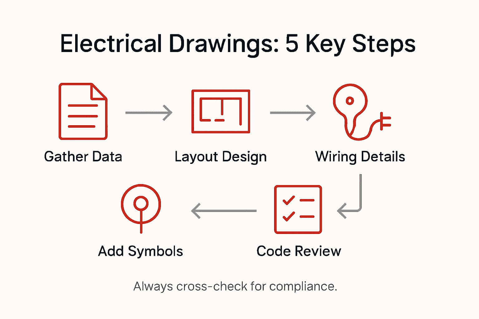
- Step 1: Gather Requirements And Project Data
- Step 2: Create Accurate Floor And Power Layouts
- Step 3: Add Symbols And Electrical Devices
- Step 4: Draft Wiring And Circuit Details
- Step 5: Verify Code Compliance And Accuracy
Quick Summary
| Key Insight | Explanation |
|---|---|
| 1. Gather Comprehensive Project Data | Understand client needs by collecting detailed information about building type, load requirements, and existing infrastructure. |
| 2. Develop Precise Electrical Layouts | Create accurate floor and power layouts based on gathered data to ensure efficiency and compliance. |
| 3. Utilize Standardized Symbols | Incorporate standardized electrical symbols in your designs to facilitate clear communication across teams. |
| 4. Create Detailed Wiring Diagrams | Document every circuit and connection with accurate specifications to enhance clarity in system interactions. |
| 5. Verify Code Compliance Thoroughly | Cross-check your designs against safety and regulatory standards to ensure reliability and prevent costly redesigns. |
Step 1: Gather Requirements and Project Data
Creating accurate electrical drawings starts with comprehensive requirement gathering. Your success depends on collecting precise project details that will guide your entire electrical design process.
Begin by scheduling a detailed consultation with your client to understand their specific needs. You will want to collect critical information including building type (residential or commercial), total square footage, electrical load requirements, power distribution goals, and any specialized equipment needs. Review existing architectural blueprints carefully and note areas requiring electrical infrastructure. Electrical drawings are technical documents that convey engineering design information about power, lighting, and communication systems.
Document every requirement systematically using a standardized project intake form. Pay special attention to voltage specifications, circuit requirements, panel locations, and future expansion plans. Take precise measurements of the space and confirm existing electrical configurations. Photograph the project site from multiple angles to capture spatial context and potential installation challenges.
Pro Tip: Always request existing electrical documentation from property owners before beginning your design process. Old blueprints and previous electrical system records can provide invaluable insights into the building’s current infrastructure and potential modification requirements.
Here’s a summary of the key data to gather at the project start:
| Data Category | Example Details | Reason for Collection |
|---|---|---|
| Building Information | Residential, 3,000 sq ft | Determines code and load needs |
| Electrical Load | HVAC, lighting, kitchen appliances | Guides panel and circuit design |
| Power Distribution Goals | Main service, subpanels | Ensures efficient power layout |
| Specialized Equipment | Server racks, medical equipment | Allows for dedicated circuits |
Step 2: Create Accurate Floor and Power Layouts
Transforming your gathered project requirements into precise electrical drawings demands careful planning and technical skill. Your goal is to develop a comprehensive floor and power layout that accurately represents the electrical infrastructure for your specific project.

Start by using comprehensive design tutorials from professional training guides to establish your drawing foundation. Begin with a clean digital blueprint of the floor plan, carefully marking precise locations for electrical panels, outlets, switches, and major power distribution points. Pay special attention to the electrical load requirements you previously documented during the requirements gathering stage. Measure and mark circuit pathways systematically, ensuring each line represents the most efficient and code compliant route.
Carefully annotate your layout with specific electrical specifications including voltage requirements, circuit breaker ratings, and dedicated circuit zones. Color code different electrical systems to distinguish between lighting circuits, power outlets, specialized equipment connections, and potential future expansion areas. Double check your measurements and ensure all markings align perfectly with the architectural plans you reviewed during the initial consultation.
Pro Tip: Always maintain a minimum 12 inch clearance around electrical panels and create a dedicated legend that explains your drawing symbols to ensure clear communication with installation teams.
Step 3: Add Symbols and Electrical Devices
Adding precise electrical symbols to your floor layout transforms your technical drawing from a basic blueprint into a professional electrical design document. Your objective is to create a clear visual representation of all electrical components and their interconnections.
Begin by referencing standardized electrical drawing symbols that ensure consistent communication across engineering and construction teams. Select symbols that accurately represent each electrical device including outlets, switches, light fixtures, circuit breakers, panels, and specialized equipment. Place symbols strategically based on your previous floor layout measurements and load requirement calculations. Use consistent sizing and orientation to maintain professional clarity. Pay special attention to national and local electrical code requirements when positioning devices and marking circuit connections.
Organize your symbols systematically by creating distinct zones for different electrical systems. Use standard color coding and line types to differentiate between lighting circuits, power circuits, communication lines, and potential future expansion areas. Include precise annotations next to each symbol indicating voltage requirements, amperage ratings, and specific circuit identification numbers. Double check that your symbol placement follows recommended spacing guidelines and allows for proper installation and maintenance access.
Pro Tip: Create a dedicated symbol legend on your drawing that explains each symbol and its specific meaning to ensure clear understanding by installation and inspection teams.
Compare the roles of common electrical drawing symbols:
| Symbol Type | Typical Use Case | Importance for Design |
|---|---|---|
| Outlet Symbol | Standard power connection | Ensures correct device placement |
| Switch Symbol | Controls lighting or devices | Defines user operation locations |
| Light Fixture | Overhead or wall lighting | Clarifies illumination planning |
| Panel Symbol | Power distribution panel | Identifies main distribution point |
Step 4: Draft Wiring and Circuit Details
Transforming your electrical layout into a comprehensive wiring diagram requires precision and systematic documentation of every circuit and connection. Your goal is to create a detailed representation of electrical flow that communicates complex system interactions clearly and professionally.
Begin by developing detailed wiring and circuit diagrams that map out single line and control wiring configurations. Start with the main electrical panel and trace each circuit pathway methodically. Document the specific wire gauge, type, and color coding for each circuit run. Mark the amperage rating and voltage requirements for every circuit, ensuring that your documentation reflects the load calculations from your earlier project requirements. Pay close attention to branching circuits, noting how power distributes from primary to secondary and tertiary connections.
Carefully annotate your wiring diagram with critical technical details including circuit breaker specifications, grounding requirements, and potential load expansion points. Use standardized symbols and line types to represent different types of electrical connections including series and parallel circuits. Color code your diagrams to distinguish between different electrical systems such as lighting, power outlets, specialized equipment, and emergency circuits. Include precise measurements and spacing to demonstrate proper installation techniques and potential interference zones.
Pro Tip: Always include a comprehensive notes section on your wiring diagram that explains any nonstandard connections or unique project specific electrical requirements to prevent potential misinterpretation during installation.
Step 5: Verify Code Compliance and Accuracy
The final and most critical phase of electrical drawing development involves comprehensive verification to ensure your design meets all safety and regulatory standards. Your objective is to create a drawing that not only looks professional but also guarantees absolute electrical system reliability and legal compliance.
Begin by carefully cross referencing your electrical drawings against the National Electrical Safety Code standards for comprehensive regulatory alignment. Systematically review each circuit, symbol, and wiring configuration to confirm they meet local building codes and national electrical regulations. Check voltage calculations, circuit load distributions, grounding specifications, and equipment spacing requirements. Pay special attention to potential code violations that could compromise safety or result in costly redesigns. Verify that wire gauges match amperage requirements, circuit breaker ratings align with load calculations, and all electrical pathways follow recommended installation practices.
Conduct a meticulous line by line review of your electrical drawings to identify any potential discrepancies or nonstandard configurations. Use a standardized compliance checklist that covers critical areas including wire routing, circuit protection, equipment clearances, and emergency system requirements. Consult with local building inspectors or electrical code experts if you encounter any ambiguous design elements. Document your verification process thoroughly to demonstrate due diligence and provide a clear audit trail for future project reviews.
Pro Tip: Create a dedicated compliance verification log that records every code standard checked and confirmed during your drawing review process.
Ensure Precision and Compliance in Your Electrical Drawings with Expert Engineering Support
Creating detailed electrical drawings involves mastering complex steps like accurate load calculations, code compliance, and thorough wiring documentation. Contractors often face challenges ensuring their plans are both precise and meet stringent regulatory standards. If you are aiming to eliminate costly errors and streamline your electrical design process with professional guidance, our engineering services are designed to help.

At Florida Licensed Engineers, we provide comprehensive electrical and building plan solutions tailored for residential and commercial projects. From expertly crafted blueprints to permitting expediter assistance and detailed inspections, our team ensures your electrical layouts are fully compliant and strategically optimized. Trust our expertise to support every phase of your design, including architectural, structural, and mechanical plans that integrate electrical systems flawlessly.
Get started today and transform your electrical drawings with confidence. Explore our services and discover how partnering with experienced engineers can save you time, reduce risk, and guarantee your projects pass every code check. Visit Florida Licensed Engineers now to connect with our specialists and schedule a consultation.
Frequently Asked Questions
What information should I gather to create electrical drawings?
To create accurate electrical drawings, you need to collect data like the building type, total square footage, and electrical load requirements. Schedule a detailed consultation with your client to document this critical information systematically.
How do I create a power layout from gathered project requirements?
To create a power layout, begin with a clean digital blueprint of the floor plan and carefully mark locations for electrical panels, outlets, and switches. Ensure that you pay attention to the documented electrical load requirements to guide your placements accurately.
What symbols should I use in my electrical drawings?
Use standardized electrical symbols to represent all components, such as outlets, switches, and light fixtures. Refer to electrical drawing standards to maintain consistency and clarity in your diagrams.
How can I ensure my wiring diagram is accurate?
Create a wiring diagram that maps out all circuit pathways and details like wire gauge and amperage ratings. Carefully document each circuit connection with precise specifications to prevent any misinterpretation during installation.
What steps should I take for code compliance verification?
To ensure code compliance, cross-reference your drawings with the National Electrical Safety Code standards. Conduct a line-by-line review of your electrical drawings and keep a compliance verification log that details every standard checked.
What should I include in my notes section on the wiring diagram?
Include critical technical details like nonstandard connections or unique electrical requirements in your notes section. This ensures clear communication and understanding for installers and inspectors.


